SOLIDWORKS PCB has been designed as a professional level design system that brings together electrical (ECAD) and mechanical (MCAD) design through collaborative interaction. The PCB design system is both easy to use and delivers a powerful set of design tools for developing electronic products, from electromechanical concept to manufacturing. Tailored to suit those unfamiliar with electronics design systems through to experienced design engineers, SOLIDWORKS PCB offers a refined design environment and an advanced set of features for bidirectional interaction with the MCAD process.
You can explore SOLIDWORKS PCB features and interface by simply experimenting with the software, by diving in to create a new design project, or better still, by first scanning through this documentation to give you a head start.
In this documentation section:
- Understanding the SOLIDWORKS PCB Environment – this page, see below.
- Driving a PCB Design through SOLIDWORKS PCB – A step by step tutorial style guide to creating a PCB design in SOLIDWORKS PCB
- Component Management – An overview of managing design components and libraries in SOLIDWORKS PCB
- Variants in SOLIDWORKS PCB – A detailed article on how to define and manage design Variants in SOLIDWORKS PCB
- Schematic Editing Strategies – Learn the basics about working in the SOLIDWORKS PCB Schematic editor
THE SOLIDWORKS PCB ENVIRONMENT
SOLIDWORKS PCB incorporates a full set of PCB design tools in a unified design environment that features a modern, easy to use design interface. User interface features that support a smooth and intuitive workflow, from schematic and PCB design through to the design release stage, include:
- A refined ribbon-style menu system
- Flexible, multi-tab design editor windows
- Dockable panels for working with design documents
- A full set of command shortcut keys
- Context-sensitive web-based Help reference
- User configuration preferences
As you move between tasks in the design workflow, the system responds to the current requirements by opening the design editors, panels and ribbon menu set that you need for the task at hand. While maintaining a consistent look and feel, the design environment dynamically changes to present the appropriate tools and windows while you design.
The user interface elements are nevertheless consistent in style, positioning, and function, and can be summarized as indicated below.

- Multiple documents can be opened for editing, each presenting with a separate Document Tab at the top of the workspace.
- As you switch from one document kind to another, for example from a schematic sheet to a PCB design, the ribbon menu and tool options automatically change.
- The commands available from the ribbon’s File tab remain the same, regardless of the document kind. This menu provides access to external file management operations and the system environment configuration preferences.
- Workspace controls such as panels can be docked along any edge of the workspace, or float on top of or beside the application.
Ribbon Command System
The SOLIDWORKS PCB ribbon-style menu provides a dynamic and highly-visual control system that allows you to find the commands you need quickly.
Commands and menus buttons are arranged in groups under a series of tabs that all change to suit the current task. The result is an efficient and easy to use command interface that makes the most use of the available screen space.
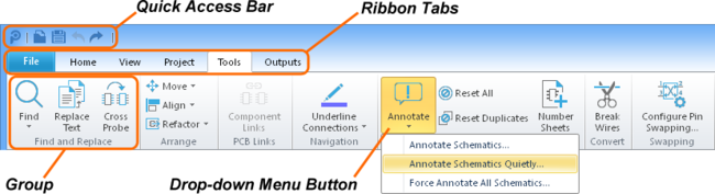
Using the ribbon menu is as simple as selecting a suitable tab, or quickly flicking through them, to find a set of commands that suit your current need.
So when editing a schematic, for example, the Cross Probe tool command is logically found within the Find and Replace group under the Tools tab. Where additional command options are available (such as Annotate Schematic Quietly, above) the button offers a drop-down menu.
In the SOLIDWORKS PCB documentation, the nomenclature for ribbon command buttons is Tab | Group | Command » Sub Menu Command, where the final command refers to a button’s (optional) drop-down menu selection. So the two examples mentioned above would be referred to as:
- Schematic Cross Probe – Tools | Find and Replace | Cross Probe, or Tools | Find and Replace |

- Annotate Schematic Quietly – Tools | Annotation | Annotate » Annotate Schematic Quietly
Note also that the ribbon’s leftmost![]() button (not a Tab as such) accesses a fixed menu for managing projects, document files and external systems (remote vault, file import, and online help). In the documentation, these commands are referred in the standard drop-down menu manner, for example File » Open Project or File »
button (not a Tab as such) accesses a fixed menu for managing projects, document files and external systems (remote vault, file import, and online help). In the documentation, these commands are referred in the standard drop-down menu manner, for example File » Open Project or File »![]()
The ribbon menu features dynamically scalable buttons that will adjust to make the most of the available menu space, such as when using SOLIDWORKS PCB on a small PC screen or at a reduced window size.

For easy access to common file and editing commands the ribbon menu features a Quick Access Bar area located above the ribbon tabs.
![]()
The Quick Access Bar provides direct commands buttons for basic file and editing tasks.
This offers buttons to directly open or save a document, and undo/redo buttons for the last edit change – hover the mouse cursor over each button to see its function hint text. The leftmost SOLIDWORKS PCB icon button ![]() provides standard window controls such as Maximize/Minimize, Close etc.
provides standard window controls such as Maximize/Minimize, Close etc.
Start page
The SOLIDWORKS PCB Start page, opened by when you first install the software, provides a central location from which to access many common system tasks and system configuration options. The page is designed to offer the simple and direct way to access routinely used areas of the software,
Access the Start page Tasks list from the ribbon’s View menu: View | Start.

- Select Start a new PCB Project to instigate a new blank project or one from the list of supplied templates.
- Select Open Project to load an existing PCB or Library project from disk.
- Select a previously opened project from the Recent Projects shortcut list to open it in SOLIDWORKS PCB.
- Select one of the supplied reference projects from the Reference Projects shortcut list to open it in SOLIDWORKS PCB.
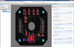
- Select Project Documents to see a graphical preview of the documents in the currently active project. Double click a preview to open the document in SOLIDWORKS PCB.
Document Windows
When you open a document, it becomes the active document in the associated editor in SOLIDWORKS PCB main design window. For example, a schematic document is opened and edited in a Schematic Editor window, a PCB library document in the PCB Library Editor window, and so on.
Multiple documents can be opened simultaneously, where each has its own selection tab at the top of the design window. Documents can occupy the entire workspace, or the workspace can be shared between multiple open documents via the Split commands in the Window menu. Documents can then be dragged from one split region to another.

Panels
More information: See the Panel references in this documentation, such as the Schematic Panels and the PCB Panels entries.
Documents store objects and entities and are edited in the main workspace. Panels are used to give an alternate view of data in the current document, for example, the PCB panel can be used to browse by Components or Nets.
Panels are also used to work across the environment, for example, the Projects panel is used to open any document in the project, as well as display the project hierarchy. Document-specific panels can only be displayed when that document-type is the active document.
All panels are accessible from the menu’s View tab.

- Panels can float in the workspace, they can be docked along the edge of the SOLIDWORKS PCB environment, or they can be set to pop out from an edge.
- Switch between multiple docked panels using the tabs at the bottom of the panel area.
![]()
- Click and drag on the panel name to move just that panel, click and drag elsewhere on the panel caption bar to move a set of stacked panels.
- Right-click on the panel name to configure its dock behavior.
- Switch a panel from docked to pop out via the pin button at the top of the panel.

FINDING HELP
SOLIDWORKS PCB provides multiple levels of help information, both locally in the software and through online documentation.
- At the immediate level, the system provides basic information via pop-up text as you hover over a control button, and most action dialogs include hints to help you configure its settings and options.
- The main in-depth help information can be accessed by simply pressing F1 over an object, editor, panel, menu entry or button. This provides a direct link to the relevant part of the SOLIDWORKS PCB online documentation.
- The menu Help button (View | Help | Help) will open the main page of the online documentation.
Shortcuts
When you are comfortable with working with the SOLIDWORKS PCB interface and design flow, a good way to streamline and speed up the process is through the use of keyboard shortcuts.
The system offers and pop-up hints for shortcuts, and a context-sensitive list of shortcuts.
- To see shortcuts for the ribbon menu Tabs, press the Alt key.
- Open the Shortcuts panel (View | Help | Shortcuts) to see a list of common keyboard shortcuts for the system and the active editor. For example, with the panel open, changing from the schematic to the PCB editor will re-populate the list with PCB shortcuts in place of Schematic shortcuts.
SYSTEM PREFERENCES
SOLIDWORKS PCB provides a centralized location for the setting of environment options across all document editors and systems – the Preferences dialog.
Access the Preferences dialog by selecting File | (located at the bottom of the File menu).
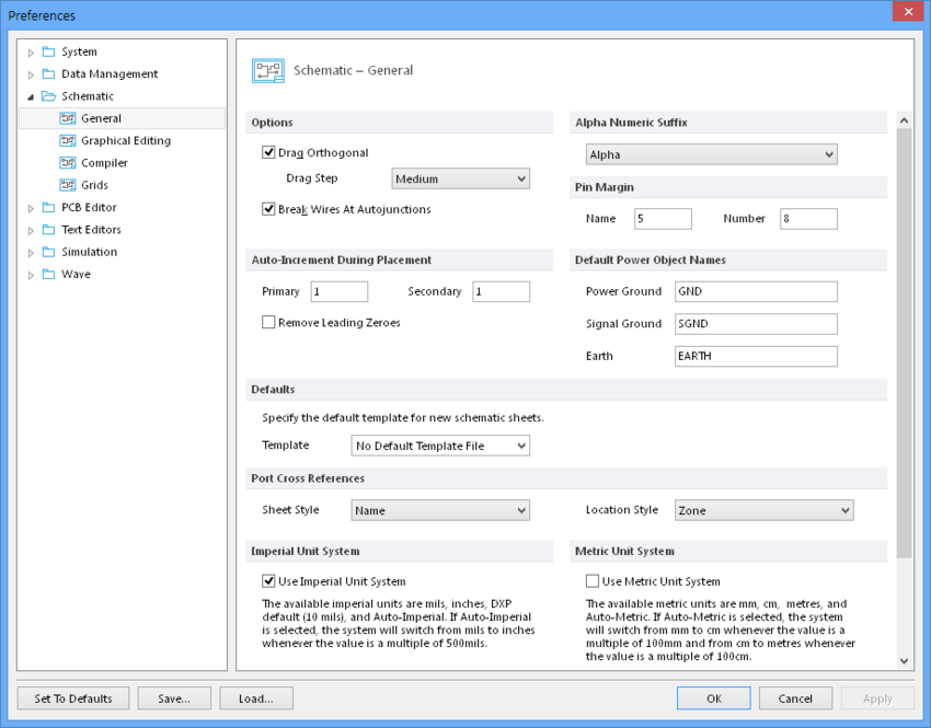
This features a tree-like navigation structure that helps you quickly find and set system-wide preferences. The current preference settings will be retained by SOLIDWORKS PCB but can also be saved or loaded to/from a single compressed format file (DXPPreferences*. DXPPrf) with ![]() and
and ![]() buttons.
buttons.
GETTING TO KNOW SOLIDWORKS PCB WORKS
A good way to become familiar with the SOLIDWORKS PCB interface, editors and command structure is to simply load one of the supplied reference designs and explore the system’s functionality with a real PCB project.
To do so, select a project entry listed under Reference Designs in the Tasks page (View | Start).
However, the best way to understand the workflow and deeper features of SOLIDWORKS PCB is by working through the documentation’s From Idea to Manufacture design tutorial guide. This provides a step-by-step explanation of how to create a complete design in SOLIDWORKS PCB and covers all aspects of the process – literally from idea to manufacturing.
If you would like more details about the advanced features of CircuitWorks, please follow our channel Logical Solutions Limited or call Logical technical support @ 040-2418 0011.
To get more updates on SOLIDWORKS Follow Us on LinkedIn: Click Here
For more details Like Us on Facebook: Click Here
For videos SUBSCRIBE to our channel: Click Here
For more information: Click Here